What Makes Kingdaflex custom hydraulic hoses Suitable for Industrial Applications?
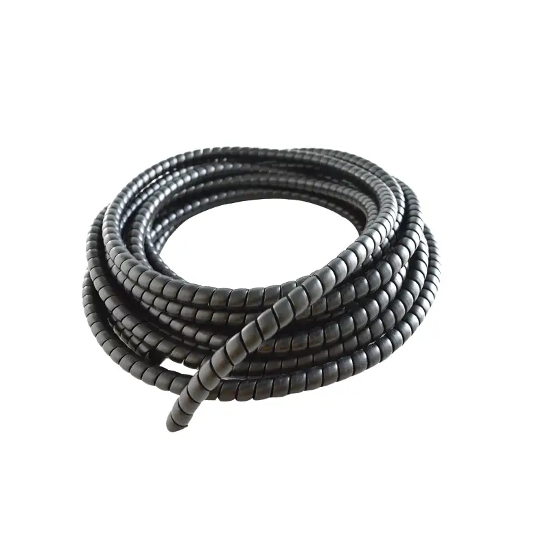
Kingdaflex custom hydraulic hoses are suitable for industrial use because the assembly can be specified around pressure, hose ID, fluid, temperature, bend radius, fitting geometry, and machine routing rather than chosen only by nominal size. For reference, a 3/4-inch SAE 100R16-type wire-braid hose can operate at 3,500 psi with a 14,000 psi minimum burst pressure, a 4:1 ratio, while a 1-inch version may operate at 2,500 psi and burst at 10,000 psi. Industrial hose construction may also cover temperatures from -40°C to +100°C and sizes from 1/4 to 2 inches, depending on the hose family and application.
Industrial hydraulic equipment does not use one pressure level across every circuit. A compact actuator line, a pump discharge line, a return circuit, and a suction line can all sit on the same machine while requiring different hose structures. A 3/4-inch high-pressure wire-braid hose, for example, may be rated at 3,500 psi, while a 3/4-inch SAE 100R4 suction-and-return hose may be rated at only 350 psi. The difference is 90% in working-pressure rating, even though both hoses have the same 19.1 mm inside diameter.
That pressure difference explains why custom specification starts with the circuit rather than hose appearance. SAE 100R16-type constructions commonly use two wire braids for high-pressure oil service, while SAE 100R4 designs can use textile reinforcement plus helical wire to prevent collapse under suction. In published industrial hose data, a 3/4-inch R16 hose has a 14,000 psi minimum burst rating versus 1,400 psi for a 3/4-inch R4 return hose, a tenfold difference created by construction and intended service.
Pressure rating alone still does not describe service life because mobile and factory equipment repeatedly cycles between lower and higher pressure. Standards such as SAE J517, ISO 1436, ISO 11237, EN 853, and EN 857 define dimensional or performance requirements for recognized hydraulic-hose families, giving engineers a common reference when specifying replacements or OEM assemblies. Commercial SAE 100R16 products are commonly cross-qualified against several of those standards rather than being described only by an internal manufacturer code.
A hose rated at 3,500 psi with a 14,000 psi minimum burst pressure has a burst level 300% above its stated working pressure. That margin is a test relationship, not permission to operate above the published working-pressure limit.
Once pressure class has been established, diameter affects both hydraulic performance and installation. Gates notes that a smaller hose ID raises fluid velocity for the same flow rate and can increase pressure drop, while longer assemblies create more frictional surface area. Fittings and adapters that change flow direction, including 45° and 90° elbows, can add further pressure loss.
That is why a custom assembly should be sized around actual flow instead of matching the outside diameter of an old hose by eye. For scale, one published R16 example uses a 19.1 mm ID and 28.2 mm OD, while a 25.4 mm ID version has a 35.3 mm OD. The larger hose provides about 78% more internal cross-sectional area, so changing one nominal size can materially change velocity and pressure-drop behavior at the same flow rate.
| Specification example | 3/4 in wire-braid hose | 1 in wire-braid hose | Why it matters |
|---|---|---|---|
| Inside diameter | 19.1 mm | 25.4 mm | Influences velocity and pressure drop |
| Working pressure | 3,500 psi | 2,500 psi | Must match circuit pressure |
| Minimum burst pressure | 14,000 psi | 10,000 psi | Both examples use a 4:1 ratio |
| Minimum bend radius | 96.5 mm | 114.3 mm | Controls routing space |
| Temperature range | -40°C to +100°C | -40°C to +100°C | Must suit fluid and environment |
Published data for these two SAE 100R16-type configurations shows why “same hose family” does not mean identical performance across sizes. Working pressure drops from 3,500 psi at 3/4 inch to 2,500 psi at 1 inch, a decrease of roughly 29%, while minimum bend radius rises by about 18%.
Routing becomes the next engineering issue after diameter. A hose that is too short can be pulled at its fittings, while excessive length can sag, rub against structures, and occupy space needed by moving parts. Gates installation guidance states that bending should not begin closer than 1.5 times the hose diameter from an end connection and advises keeping bends at or above the specified minimum radius.
A real dimensional example makes the routing requirement easier to see. A 3/4-inch R16 hose can have a 96.5 mm minimum bend radius, while a 1.25-inch version may require 210 mm, more than 117% larger. A designer replacing one hose size with another therefore cannot assume that the same routing path will remain acceptable, even when both products belong to the same general high-pressure family.
Fitting orientation matters for the same reason. Straight, 45°, and 90° ends allow an assembly to meet ports without forcing the hose into an immediate bend, but angled fittings must be clocked correctly when both ends are fixed. Installation guidance also warns against twisting a hose because applied pressure can contribute to assembly failure or connection loosening.
A custom hose should arrive with its length, end connections, and angular orientation already defined. For a maintenance team changing 40 assemblies across a machine fleet, even a 5% mismatch rate would produce two assemblies requiring rework, replacement, or routing changes.
Material selection follows mechanical layout because the inner tube remains in continuous contact with the fluid. Nitrile-based tubes are widely used with petroleum hydraulic oils, while some constructions are also listed for phosphate-esters and water-glycol fluids. Thermoplastic SAE 100R7 hose may use a seamless nylon tube, polyester braid, and urethane cover, showing how material systems can differ significantly even when both products carry hydraulic fluid.
Temperature narrows the acceptable material choice further. Published wire-braid hose examples operate from -40°C to +100°C, while water, water-oil emulsions, and water-glycol solutions can have lower permitted temperature limits depending on hose family. Gates lists some pressure-line constructions at +93°C and others at +107°C for those media and states that the lower limit should be used when fluid and hose temperature limits differ.
A 7°C or 14°C temperature difference may look small in a specification table, but industrial machines can operate for 8, 12, or 24 hours per day near heat sources. Routing guidance therefore recommends moving hoses away from high-temperature components or insulating them where separation is not possible. Temperature selection should cover both the conveyed fluid and external heat around engines, furnaces, compressors, and enclosed hydraulic power units.
Abrasion creates another selection boundary, especially on excavators, agricultural machines, lifting equipment, mining machinery, and material-handling systems. Hose covers may resist oil and weather, but repeated rubbing can still remove cover material and expose reinforcement. Gates specifically recommends routing hoses away from rubbing surfaces and using correctly sized clamps on long runs because an oversized clamp can allow repeated movement inside the support.
For machinery with hundreds of operating hours per month, small routing improvements can remove thousands of repeated contact events. A cylinder hose that flexes 20 times per hour over a 10-hour shift completes 200 movement cycles per day; over 250 working days, that becomes 50,000 cycles at the same bend and contact points. Custom length and fitting geometry reduce unnecessary movement before additional sleeves or guards are considered.
The same specification discipline applies when buyers source Kingdaflex industrial hoses alongside hydraulic assemblies. Industrial hose requirements can extend beyond high-pressure oil service into suction, return, air, water, material transfer, or other media, so hose construction should follow the actual pressure, vacuum, fluid, temperature, and external environment rather than a single catalog category.
OEM work adds repeatability to the requirement. If an equipment builder produces 500 machines per year and each machine uses 12 hydraulic assemblies, purchasing controls cover 6,000 assemblies annually. A 1% dimensional or fitting error would affect 60 assemblies, so drawings should define cut length, finished assembly length, fitting references, angle orientation, hose standard, pressure class, and any protective sleeve or labeling requirement.
Replacement work needs similar discipline because “matching the old hose” may preserve an earlier installation problem. Maintenance teams should record hose ID, port type, thread or flange form, overall assembly length, fitting angle, operating pressure, fluid, temperature, minimum bend radius, movement, and abrasion exposure. An assembly with a 2,500 psi working rating and 10,000 psi burst rating should not be substituted simply because another hose has the same 25.4 mm ID.
Procurement teams can also compare specifications numerically instead of using broad descriptions such as “heavy duty.” A 1.5-inch R16-type hose may be rated at 2,000 psi with an 8,000 psi minimum burst pressure and a 250 mm minimum bend radius, while a 1.25-inch version may carry 2,300 psi and require 210 mm bend radius. The larger example has about 13% lower working pressure and roughly 19% more required bending space.
Those figures show why custom hydraulic hose selection works best as an assembly specification rather than a product-name exercise. Pressure class, reinforcement, ID, temperature, fluid compatibility, bend radius, overall length, connection standard, fitting angle, cover protection, and routing condition can all be documented before production. For industrial machines expected to run hundreds or thousands of hours per year, controlling those dimensions and operating limits provides a more repeatable basis for hose purchasing, installation, inspection, and replacement.